Snake in Hardware
This whole thing runs without a CPU. Every move the snake makes is decided by wires and gates, all at once, on each clock tick. It’s about 100 nodes of logic, registers, and memory, all written in TypeScript and simulated live in your browser. The same code exports to Verilog. Here’s how it works.
Pixels & Memory
The screen is just memory. One byte per pixel across an 8×8 grid, and setting a byte to 1 lights that pixel up. The catch: the game has to write pixels while the display reads them, at the same time. A DualPortRAM gives us exactly that, two independent windows into one block of memory. Port A is where game logic reads and writes; port B feeds the Screen, which scans the addresses to draw the grid.
Addresses run left to right, top to bottom: 0 is top-left, 7 is top-right, 63 is bottom-right. The pattern below draws a border.
Toggle write-enable, set an address and data, then Tick to write a pixel; the HexDisplay shows what reads back. Snake runs this same cycle every frame.
From Coordinates to Pixels
The snake moves on a 2D grid, but the framebuffer is a flat array of 64 bytes. We convert (X, Y) to a linear address: address = (Y « 3) + X.
Multiplying by 8 is a left shift by 3, and in hardware a constant shift costs zero gates. It’s just wiring. Each bit of Y connects three places higher, the low three bits tied to zero. The only real gate is the final Adder for X.
Change X and Y below. At (3, 2) you get address 19, row 2 column 3.
Decoding Player Input
Arrow keys produce scan codes: Up 72, Down 80, Left 75, Right 77. The circuit turns these into movement deltas deltaX and deltaY, each −1, 0, or +1.
Four Comparators check the code against each direction. Their outputs feed a Mux tree that picks the delta: Left sets deltaX to 255 (−1 in unsigned 8-bit), Right sets it to 1, otherwise 0. deltaY works the same for Up and Down.
Set the key code below to 72, 75, 77, or 80 and watch the two delta displays flip between −1, 0, and +1.
Moving a Pixel
Now make a pixel move. Two Registers hold the head position, headX and headY, both starting at 4. Each tick adds the deltas to get the next position.
The grid wraps: walk off the right edge and you reappear on the left. That comes for free by keeping only the lowest 3 bits of each coordinate, which forces it back into the 0–7 range. Column 7 + 1 wraps to 0; column 0 − 1 wraps to 7 (0 − 1 = 255, and 255 & 0b111 = 7). The part doing it is a BitSlice, and there’s no edge-case check anywhere; the wrap falls out of the arithmetic.
The wrapped coordinates become a pixel address (Y×8+X) written to the framebuffer. Flip enable on, set a direction code, and tick to walk the pixel across the screen.
Multi-Step Operations
A RAM port does one thing per cycle: read or write, at one address. But moving the snake needs four memory operations: read the tail’s address, clear that pixel, write the new head to the body buffer, draw the new head pixel. So we run four phases.
A 2-bit register counts the phase, ticking 0 → 1 → 2 → 3 and back to 0. It only holds two bits, so it wraps after 3 on its own (a BitSlice keeping the low two bits). Comparators watch the count and switch on the right RAM operation for each phase.
Toggle enable and tick to watch the counter cycle; each LED marks its phase. In the full game, the four ticks make one complete “game step.”
Eating Food
When the head lands on the food, the snake grows by one segment and the food respawns. To catch that, compare head X to food X and head Y to food Y. If both match, it’s a hit.
Two Comparators produce equality flags; an And gate combines them into a collision signal that drives a “grow” flag, 1 on a hit and 0 otherwise.
In the full game, grow suppresses the tail for one step: the head advances, the tail stays, so the snake gets one longer. Match the coordinates below (or don’t) and watch the collision LED.
The Full Snake Game
Everything from the sections above is one circuit now: framebuffer, addressing, the phase pipeline, collision detection, the lot. The full Snake circuit is about 300 lines of TypeScript, compiled and running in your browser.
The body is a circular buffer of pixel addresses in RAM 64–127. The four phases: phase 0 reads the tail address, phase 1 clears the tail pixel, phase 2 writes the new head address, phase 3 draws the new head. Eating food suppresses the tail clear, so the snake grows.
In case you want to play again…
Fair warning: it has bugs. The snake can turn back the way it came and run straight into itself, and you’ll find other rough edges if you go looking. That’s part of the charm of building a game out of gates instead of code.
Want to take it apart? Open the whole circuit in the editor to trace every wire, change it, and break it however you like.
From Browser to FPGA
The same TypeScript you’ve been poking at runs on silicon too. Export it to Verilog, synthesize it, and it runs on an actual FPGA. Here it is on a ULX3S (Lattice ECP5), drawing to a monitor over HDMI, steered with the board’s buttons.
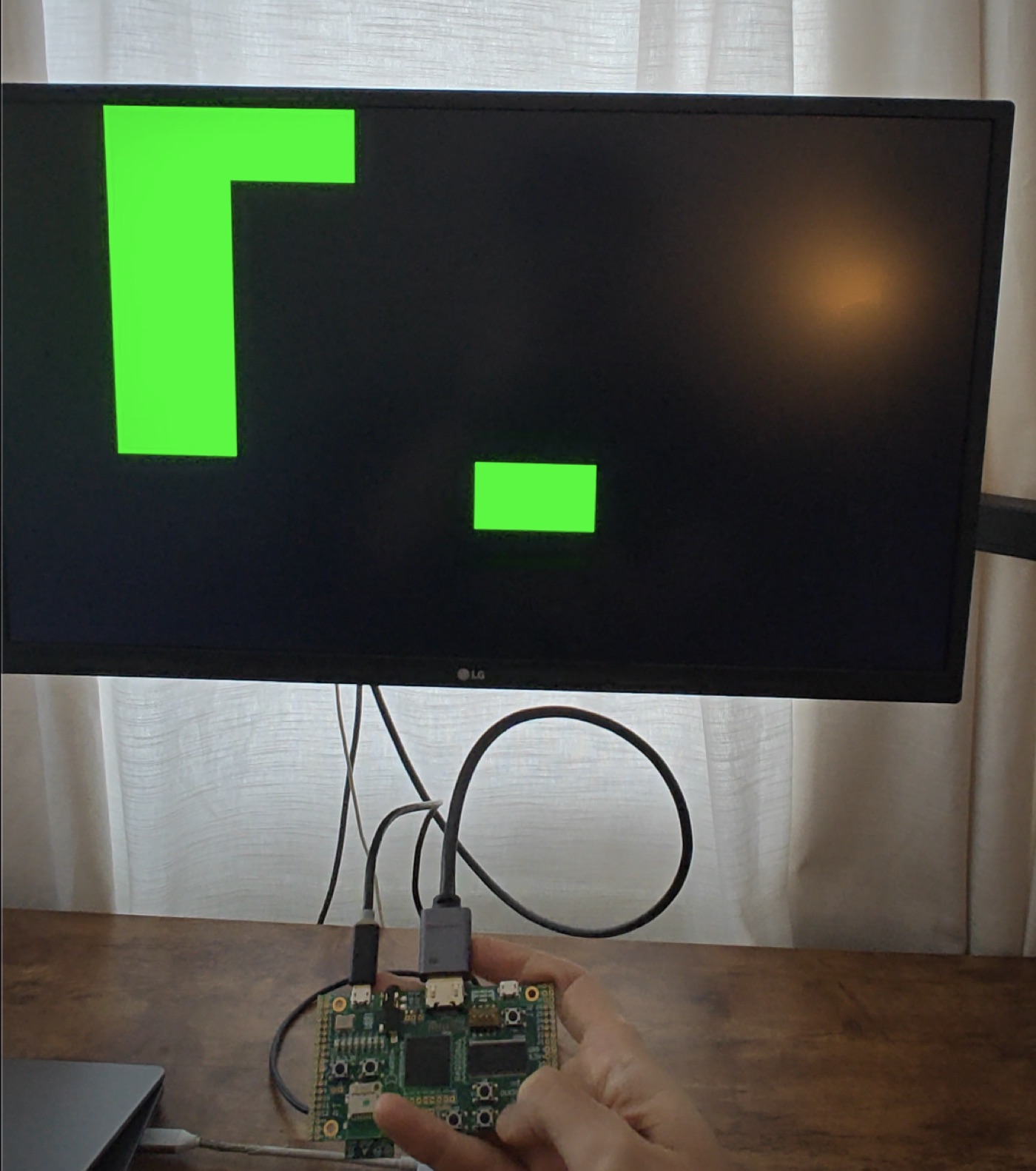
This isn’t a Verilog rewrite of Snake. The game logic and framebuffer are byte-for-byte the circuit you just played, and a CI check fails the build if the browser version and the bitstream ever drift apart.
The video is generated logic too, no display chip in the path. A TMDS encoder turns each pixel into the 10-bit DVI signaling the monitor expects. That, plus the pixel clock and button inputs, is plain Verilog wrapped around the generated core, the same plumbing any ULX3S video project uses. The game is the generated part; this is just the wiring to get it on a screen.
The flow is open the whole way: Verilog → Yosys (synth_ecp5) → nextpnr → ecppack → bitstream. About 100 nodes of logic, and nextpnr closes timing with plenty of headroom over the 25 MHz the design actually runs at.
Run it on your own board
Got an FPGA? The Snake core is plain Verilog, so it synthesizes for any board. The repo has a complete ULX3S (ECP5) build to copy from, plus a README on running it there and porting it elsewhere: you swap the wrapper, the constraints, and the toolchain target, while the game logic stays the same.